In the context of the
![]() Envisionment and Discovery Collaboratory
,
we have been working to create an action space that
supports more direct interaction of a group of individuals with
computational simulations in a face-to-face environment.
This has led to the development of the "Participate-in-the-Action (PitA)"-Board.
Envisionment and Discovery Collaboratory
,
we have been working to create an action space that
supports more direct interaction of a group of individuals with
computational simulations in a face-to-face environment.
This has led to the development of the "Participate-in-the-Action (PitA)"-Board.
Initial prototypes of the EDC system were based on a touch-screen
technology (![]() SmartTech's SmartBoard) placed
in a horizontal orientation, which afforded insights into important
aspects of the around-the-table interaction. This revealed several
limitations, such as problems with simultaneous interactions and the
inability to create interaction behaviors more closely tailored to the
objects the user is interacting with.
SmartTech's SmartBoard) placed
in a horizontal orientation, which afforded insights into important
aspects of the around-the-table interaction. This revealed several
limitations, such as problems with simultaneous interactions and the
inability to create interaction behaviors more closely tailored to the
objects the user is interacting with.
We are currently using a technology created for electronic chessboards
(by ![]() DGT Projects, NL) that allows
several objects (with embedded transponders) to be tracked
simultaneously. Each object can then be given a particular form of
behavior by the software system.
DGT Projects, NL) that allows
several objects (with embedded transponders) to be tracked
simultaneously. Each object can then be given a particular form of
behavior by the software system.
To restore the sketching capability that the new system lacks, we are
working with electronic pen technology that will allow users to
"sketch" their ideas and define objects within a simulation (![]() eBeam).
eBeam).
We are exploring the use of this technology in numerous contexts where collaborative or participative interaction is a critical aspect of the design process. Possibilities that are being investigated include:
PitaSim is constructed using ![]() Squeak, a Smalltalk media environment. The use of
Squeak, a Smalltalk media environment. The use of
![]() Squeak allows
for the rapid development of a graphical interface, hardware drivers
and network connections.
Squeak allows
for the rapid development of a graphical interface, hardware drivers
and network connections. ![]() Squeak allows for relatively easy creation
of simulations, such that real world situations can be modeled by simply
defining a few objects and their relationships to each other.
Squeak allows for relatively easy creation
of simulations, such that real world situations can be modeled by simply
defining a few objects and their relationships to each other. ![]() Squeak runs on a
virtual machine, enabling almost any system to run any one of the PitA
servers and clients.
Squeak runs on a
virtual machine, enabling almost any system to run any one of the PitA
servers and clients.
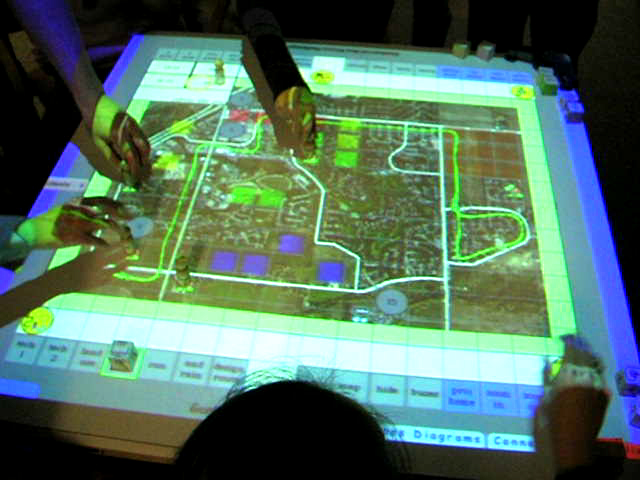
The current PitA-Board is composed of 4 ![]() DGT Projects chessboards linked together and placed in a
custom table. Each of the chess pieces contains an RF circuit with a
unique signature that allows for 15 different unique inputs per
context, and any number of pieces with the same signature. The board
is limited in its immediate resolution to the chessboard square size,
but provides an advantage over the older models in that several users
may input to the simulation simultaneously. An overhead projector
linked to the PitA simulation server provides the users with visual
feedback on the board, and outlines the grid that a piece may be
placed into.
DGT Projects chessboards linked together and placed in a
custom table. Each of the chess pieces contains an RF circuit with a
unique signature that allows for 15 different unique inputs per
context, and any number of pieces with the same signature. The board
is limited in its immediate resolution to the chessboard square size,
but provides an advantage over the older models in that several users
may input to the simulation simultaneously. An overhead projector
linked to the PitA simulation server provides the users with visual
feedback on the board, and outlines the grid that a piece may be
placed into.
In the interest of allowing the technology to be used to support the integration of personal and shared interaction spaces, a PDA client was created to disperse information and voting control to a larger group of participants. As conceived, the PDA client would allow participants to interact with information on an individual basis as well as in the shared interaction space. Each client also has the ability to electronically announce its presence so that the simulation would be aware of a new participant, and be able to send a summary of the simulation thus far so that the user may get caught up.
A secondary use for the PDA client is for input to the simulation. A user may place a piece or "wand" onto the space in the simulation he or she wishes to modify. That user's PDA will then be granted permission to modify the space or any object occupying that space. Given this scenario, one can imagine one of many uses being for the user to be able to specify certain information about his or her own house. By placing the wand on his or her house, the user might then be prompted to enter information such as number of occupants, cars, etc on his PDA.
Previous use of ![]() SmartTech's SmartBoard
supported sketching as well as interaction with the simulation.
The sketching functionality was lost when we began to use
the
SmartTech's SmartBoard
supported sketching as well as interaction with the simulation.
The sketching functionality was lost when we began to use
the ![]() DGT Projects chessboard
interface. After conducting a few tests of the new interface, several
of the participants who had been involved with testing the previous
system indicated that the sketching feature was useful and should be
re-incorporated into the new system.
DGT Projects chessboard
interface. After conducting a few tests of the new interface, several
of the participants who had been involved with testing the previous
system indicated that the sketching feature was useful and should be
re-incorporated into the new system.
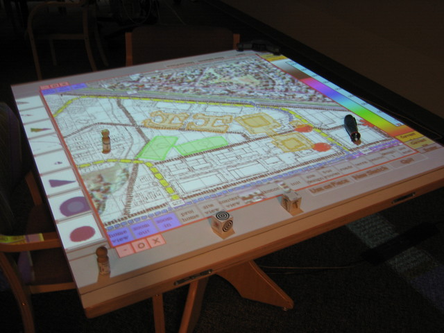
In order to add sketching to the new system, an ![]() eBeam electronic
whiteboard was added. This tracks the movements of a special
pen on the surface and sends the results to an attached computer. In order
to avoid adding too much complexity to the user interface, the pen is currently
used in a mode that interprets pen movements as mouse movements (thus only one
pen can be used at a time). This input provides a very different form of
collaboration than the chessboard. Instead of allowing multiple users to make
changes at will, the pen interface forces someone to be in charge of making the
current changes. In this manner, a new form of social creativity is observed as
the users may express their ideas, and then pass control to another user who may
add to or modify the existing sketch. We are also exploring how the use of multiple pens might be incorporated.
eBeam electronic
whiteboard was added. This tracks the movements of a special
pen on the surface and sends the results to an attached computer. In order
to avoid adding too much complexity to the user interface, the pen is currently
used in a mode that interprets pen movements as mouse movements (thus only one
pen can be used at a time). This input provides a very different form of
collaboration than the chessboard. Instead of allowing multiple users to make
changes at will, the pen interface forces someone to be in charge of making the
current changes. In this manner, a new form of social creativity is observed as
the users may express their ideas, and then pass control to another user who may
add to or modify the existing sketch. We are also exploring how the use of multiple pens might be incorporated.
The sketching interface involves a color and height picker, a library, and a collection of objects that store the current sketched information. The color picker allows the user to determine the fill color (which can be none for a line) and line color they wish to draw with. The user may also select to change the pen to an eraser. Once the color and height of the sketched object has been determined (height being used in the 3D visualiation mentioned below) the user must still create a new "sketch" before drawing in the action space. Each sketch is a separate object of which a limited number may be stacked upon each other at a time to provide several layers of overlaid sketches. Furthermore each sketch may be saved to and restored from the library object. The library allows for the further option that sketches may created and stored before a presentation and restored to match the context of the conversation later on.
A further option is available to the user to use a sketch as an actual object in the simulation. By pressing the "make object" button with the pen and selecting a line or filled object from the sketch, the object is then imported to the simulation and can be used as any object, depending on the context of the situation and the desires of the creator of the simulation.
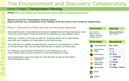
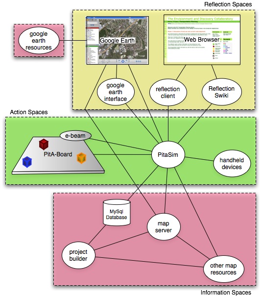
The reflection space is a separate client that connects to the simulation through a TCP link. It is mainly a web client, which takes its cues from the progression of the simulation. As a certain point in the simulation is reached, or a particular piece is used, the reflection space will provide pertinent information. This information can either be pre-stored by an expert in the field, or can be fetched in real time from the web. The idea of the space is to provide useful information to the simulation participants so that they may "reflect" upon the action that they just performed. The space may also be used to keep stats about the simulation such as average bus stop wait time per passenger, percent of land used for particular applications, etc.
The ability to change perspective in an urban planning project is an obvious necessity. Early work on this extension was done using OpenGL. A "visualization server" would connect to the "simulation server" through a TCP socket allowing for the exchange of data during the simulation. Libraries from Coin were used to allow the user to create VRML objects for use in the visualization. This project has been set to the side currently, but is still under consideration for its usefulness in conjunction with a CAVE environment.
Its replacement is a visualization using ![]() Google Earth. By providing KML server objects from the
simulation, view control, 3D objects and image overlays can be relayed
to a
Google Earth. By providing KML server objects from the
simulation, view control, 3D objects and image overlays can be relayed
to a ![]() Google Earth client. The current solution employs three
separate sockets to handle three of the data streams, each of which is
refreshed by the
Google Earth client. The current solution employs three
separate sockets to handle three of the data streams, each of which is
refreshed by the ![]() Google Earth client on a
periodic basis. By providing this stream separation, the end user can
subscribe to the data he is interested in, and can turn off various
streams, such as view control, so that he may change the perspective to
his personal preference.
Google Earth client on a
periodic basis. By providing this stream separation, the end user can
subscribe to the data he is interested in, and can turn off various
streams, such as view control, so that he may change the perspective to
his personal preference.
The KML feeds have been separated as follows:
Immediate 3D visualization is available through a local ![]() Google
Earth client, which is projected for all participants to
observe. Control of the view is done through two designated pieces,
and the context of the 2D view. The "camera" for the
Google
Earth client, which is projected for all participants to
observe. Control of the view is done through two designated pieces,
and the context of the 2D view. The "camera" for the ![]() Google
Earth client is centered on the same location as the 2D view, and
is positioned according to the location of the designated pieces. The
view pieces differ only in view angle, one of which provides a
"helicopter" view and the other provides a ground level view. As the
2D view is zoomed in or out, the range of the camera from the center
point is decreased or increased respectively, effectively providing
the same scaled view as the 2D version.
Google
Earth client is centered on the same location as the 2D view, and
is positioned according to the location of the designated pieces. The
view pieces differ only in view angle, one of which provides a
"helicopter" view and the other provides a ground level view. As the
2D view is zoomed in or out, the range of the camera from the center
point is decreased or increased respectively, effectively providing
the same scaled view as the 2D version.

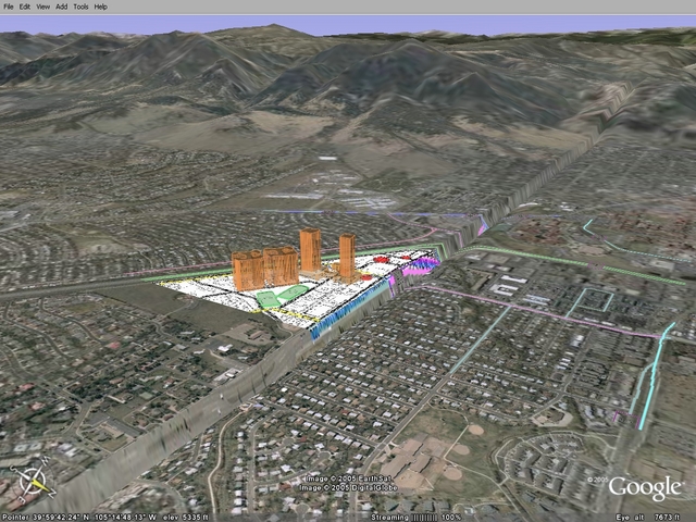
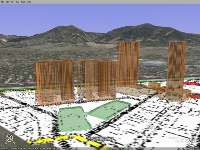
All of the sketches, as mentioned before, have an associated height. As can be seen in the sketching image above, the buildings have been sketched into the simulation using the pen. When these are shown in a Google Earth 3D view, the height differences become evident, allowing participants to better visualize the impact of their design conjectures. Note the overlay identical to that used in the action space has been placed beneath the sketched buildings in the Google Earth view.
Multiple clients can be supported to provide remote meeting
capabilities, and further capability can be added by using the PDA
client (mentioned above) with a ![]() Google Earth client.
Google Earth client.